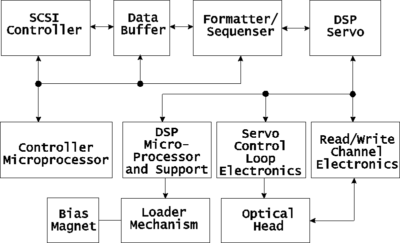
Figure 1. 2X drive functional diagram

Figure 1. 2X drive functional diagram
There are four major sub-assemblies within the optical drive: the controller PCA, servo PCA, loader mechanism, and the optical head.
Controller PCA
The controller PCA is a microprocessor-based collection of digital electronics that handles functions performed by a SCSI controller, a data buffer, and a formatter/sequencer.
SCSI Controller
The SCSI controller provides the SCSI interface connection to the host computer.
This interface consists of both the electrical signals and the firmware which decodes the various commands and messages on the SCSI bus and instructs the drive to take appropriate action.
Data Buffer
The data buffer and associated control electronics provide a buffer to speed match transfers to and from the host computer and the optical disk. The data buffer provides a cache for read and write operations, optimizing the speed of these transfers. The HP C1716T drive contains 512 Kbytes of buffer RAM.
Formatter/Sequencer
The formatter/sequencer function formats and decodes data for read and write transfers. During a write function user data is sent via the SCSI bus. The formatter converts the parallel data into an encoded serial bit stream that includes all the format and error correction features required to meet the ANSI and ISO specifications. During reads, the decoder converts the serial data stream, which includes format and error correction features, into parallel data.
Servo PCA
The servo PCA includes a digital signal processor (DSP) that controls the actions of the many servo loops that interact with the optical head and the loader assembly.
DSP Microprocessor and Support/Servo Control Loops
Most of the electronics on the servo PCA is analog circuitry. This circuitry is designed into the control loops of the following servos: spindle motor/speed, laser power control, track following, seek/position maintenance, focus actuation, fine position actuation, and coarse position actuation. Whenever the drive is performing a read or write operation, all these servos are activated.
Also on the servo PCA are control electronics for the loader assembly. Included are drivers for the loader and spindle (speed control) motors, sensor circuitry for the cartridge loaded and write protect detectors, LED drivers for the control panel LEDs, and control circuitry for the bias magnet subassembly of the loader mechanism.
Read and Write Channel Electronics
Read channel electronics take analog data from the optical head and convert it into digital "transitions". These transitions are decoded by the decoder electronics on the controller PCA in order to extract data from format and error correction features. The write channel electronics take the serial data stream from the formatter/sequencer and convert the digital pulses into analog data. This analog data is then sent to the optical head.
Mechanism Assembly
Loader Mechanism
The loader mechanism consists of two motors: a spindle motor for speed control and a loader motor for loading and unloading of the cartridge. The loader motor includes a gear train and rack-and-pinion system that allow the cartridge shuttle to raise and lower the cartridge within the loader housing. The bias magnet sub-assembly sits on top of the cartridge shuttle and provides the correct polarity for erasing or writing data.
Optical Head
"Split optics" design. This design physically separates the laser diode and its associated detectors from the focus/fine position actuators, providing significant seek time performance advantage due to less mass on the moving portion of the optical head.
There are several actuators in the optical head. The coarse position actuator moves the focus/fine position actuators to the vicinity of the desired sector on the optical disk. The fine actuator makes small corrections (+/-25 tracks) to center the optical head on the desired sector. The focus actuator then moves up and down to provide optimal focus on the light beam. All these actuators, and the laser diode (and its detectors) are controlled by the servo PCA.
The laser diode and its associated detectors are part of a flex circuit on the optical head assembly. On this flex circuit are analog electronics which further condition the control signals for the laser diode, and pre-amplifiers for the servo and data control signals that are returned to the servo PCA.
Сэкономленное на переводе время, уходит на подготовку завершающей (надеюсь) статьи. Похоже, она тоже будет на английском ;-).
Максим Осташов
Размещено на www.s12most.mailru.com 8 апреля 2001
Есть вопросы или дополнения, конструктивная критика? Пишите!